Every commercial heat pump plant has a mismatch problem: the machine’s minimum output rarely matches the building’s minimum load. When the load drops below what the compressor can turn down to, the heat pump starts, satisfies the loop in minutes, and shuts off — over and over. That short cycling is the single most common field failure mode in commercial heat pump retrofits, and the buffer tank is the component that prevents it. Undersize it and the compressor pays; oversize it blindly and you’ve bought steel and floor space that never earn their keep.
In short: A commercial heat pump buffer tank is sized from the minimum run time you want to guarantee the compressor, using V = t × (Qmin output − Qmin load) / (∆T × 500), where V is gallons, t is minutes, Q values are in Btu/h, ∆T is the allowable tank temperature swing in °F, and 500 converts pounds of water and minutes into the answer.
Rules of thumb — commonly 2 to 5 gallons per ton for commercial hydronic systems — are starting points for budgeting, not sizing. And in domestic hot water plants, the right question is often not “how small a buffer can I get away with” but “how much storage lets me run a smaller heat pump” — the tradeoff at the center of every central heat pump water heater design.
In this article
A buffer tank is a volume of water piped between the heat pump and the distribution system. It does three things at once: it adds thermal mass so the compressor runs long enough per cycle to be healthy, it hydraulically decouples the heat pump’s required flow rate from the distribution loop’s flow rate, and it smooths supply temperature during defrost cycles and load swings.

Short cycling is the enemy. A compressor that starts, runs four minutes, and stops — dozens of times a day — suffers accelerated bearing and contactor wear, loses efficiency to start-up transients, and can nuisance-trip on its own protection logic. Modern inverter-driven commercial units turn down further than older single- and two-stage machines, which shrinks the problem but does not eliminate it: below the inverter’s minimum modulation, the machine is back to on/off operation, and the buffer tank carries the load between cycles.
In multifamily and commercial domestic hot water plants, the same physics shows up under a different name. The U.S. Department of Energy’s Building America guide to central heat pump water heater systems for multifamily buildings documents how these systems pair single-pass or multi-pass heat pumps with dedicated storage and temperature-maintenance tanks, precisely because a heat pump sized to meet peak draw directly would be enormous, electrically demanding, and heavily cycled the rest of the day.
Two details that separate a real sizing from a guess. First, the formula returns total required system volume — water already sitting in piping and emitters counts, so the buffer tank only makes up the shortfall. Second, if the loop runs glycol, the 500 constant drops with the fluid’s specific heat and density, and the required volume grows accordingly. Smaller ∆T — tight process control or chilled-water dehumidification, for example — also grows the tank fast; the relationship is inverse and unforgiving.
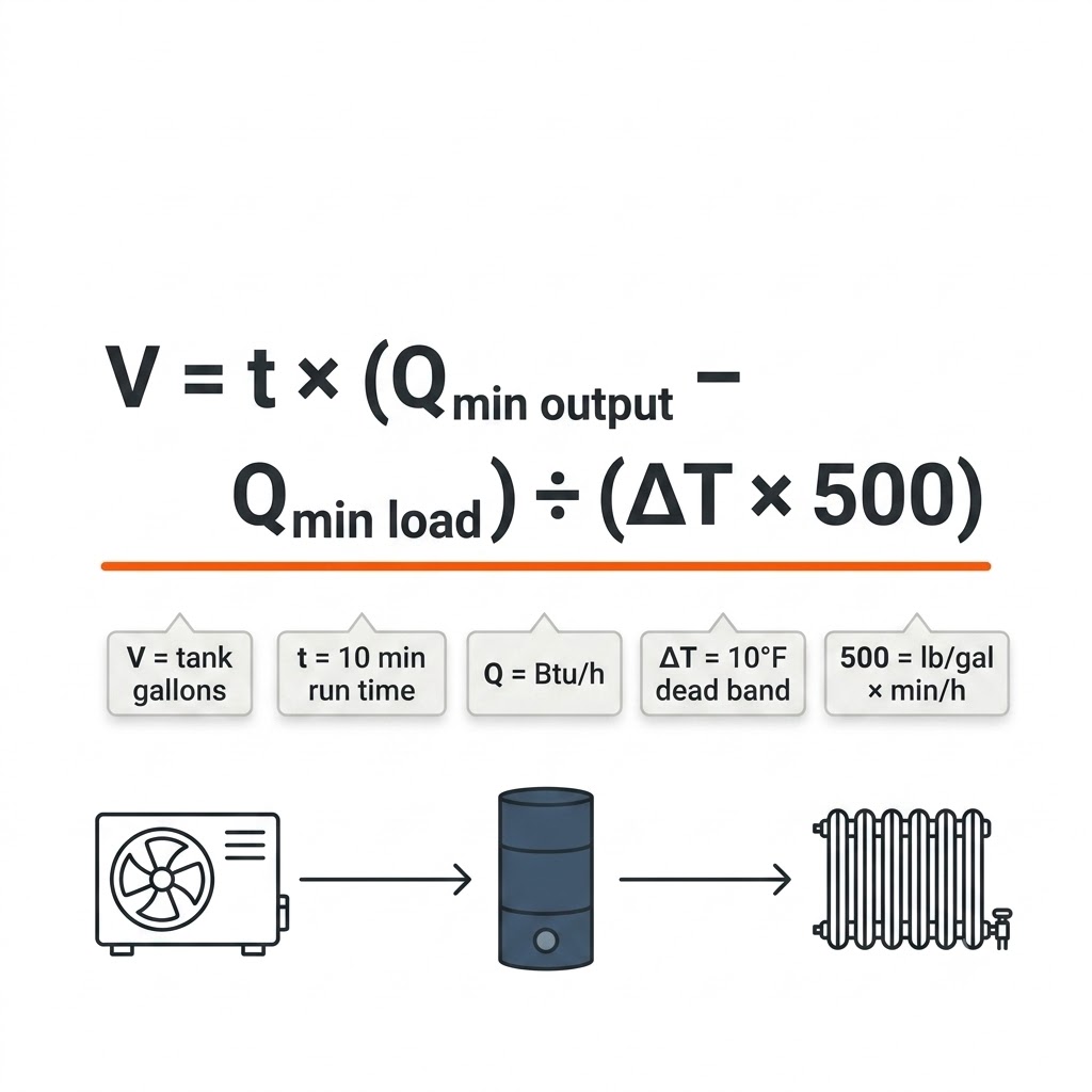
Commercial buffer tank sizing inputs
InputWhat it isWhere it comes from
V (gallons)Required active system water volumeThe result — subtract existing loop volume to get tank size
t (minutes)Desired minimum compressor run time per cycleManufacturer requirement; ≈10 minutes is a common commercial target
Qmin output (Btu/h)Heat pump output at its lowest stage or minimum inverter modulationEquipment submittal — nameplate capacity ÷ turndown ratio
Qmin load (Btu/h)Smallest load the system can presentSmallest zone calling alone; load calculation or zoning schedule
∆T (°F)Allowable tank temperature swingControls design — ≈10°F is typical for heat pumps to protect COP
500Conversion constant8.33 lb/gal × 60 min/h for water; adjust for glycol
Run the arithmetic and the rules of thumb reveal their hidden assumptions: roughly an hour of load coverage at a ≈20°F swing for the largest, a bare minimum-cycle band for the smallest. When your equipment, dead band, or load profile differs from those assumptions — and in commercial work it almost always does — the formula wins. Use gallons-per-ton to sanity-check a budget line, never to stamp a drawing.
Commercial buffer tank rules of thumb
Rule of thumbTypical contextFailure mode
2–5 gal per ton of heat pump capacityCommercial hydronic heating/cooling, US practiceIgnores turndown ratio — a 3:1 machine and a fixed-speed machine get the same tank
≈10 L per kW (≈0.8 gal per 1,000 Btu/h)European ASHP guidance, often quoted for R290 unitsManufacturer-specific; several now publish their own curves instead
≈25 L per kW (≈2 gal per 1,000 Btu/h)Conservative thermal-store sizing, low-turndown plantCan more than double the vessel versus formula sizing on high-turndown equipment
Take a 30-ton (360,000 Btu/h) air-to-water plant built from two 15-ton inverter units, each modulating down to 40% — so the minimum sustainable output with one unit running is 72,000 Btu/h. The smallest zone that can call alone presents 20,000 Btu/h. The manufacturer wants 10-minute minimum cycles, and controls allow a 10°F dead band:
V = 10 × (72,000 − 20,000) / (10 × 500) = 104 gallons of required active volume
If the primary loop and air handler coils already hold 40 gallons, the buffer only needs to supply the remaining ≈64 gallons — one 80-gallon module with margin to spare. Cross-check against the rule of thumb: 2–5 gal/ton × 30 tons = 60–150 gallons of total volume, and the formula’s 104 sits comfortably inside the band. When the two methods disagree sharply, trust the formula and find out which assumption broke. Full dimensions and connection schedules for the 80-gallon module are on the modular thermal storage tank specifications page.
The distinction matters because the sizing logic inverts as you move down the table. A buffer tank is sized to be as small as safely possible. Primary storage is sized to be as large as economically useful: research presented at the ACEEE Summer Study on large-capacity CO2 heat pump water heating makes the tradeoff explicit — meeting a given peak with less storage requires more heat pump capacity, and an electrically constrained building may deliberately maximize storage to minimize connected load. Conflating the three tank types produces systems that either cycle themselves to death or leave demand-charge savings on the table.
Buffer, swing, and primary storage tank roles
TankSystemJobGoverning sizing logic
Buffer tankHydronic space heating / coolingPrevent short cycling; hydraulic decouplingMinimum run-time formula
Swing / temperature-maintenance tankCentral heat pump water heating (CHPWH)Carry recirculation loop losses so the primary heat pump doesn’t cycle on themLoop loss × safety factor; runtime checked against a ≈20-minute threshold
Primary storageCHPWH / process / solar thermalMeet peak draw from stored energy; shift load to cheap or solar hoursPeak event volume versus generation rate; capacity-storage tradeoff
For commercial and multifamily domestic hot water, the industry-standard starting point is the Ecosizer CHPWH sizing tool — free, built by Ecotope with California utility funding, and cataloged by the DOE’s Building America Solution Center. Its methodology sizes primary storage from a worst-case peak event: assume the tank has drawn down to just above the aquastat when the morning peak begins, then size the remaining volume to cover the gap between the peak draw and the heat pump’s generation rate, with compressor runtime capped at 16 hours per day.
Three Ecosizer concepts every commercial designer should hold onto. The aquastat fraction — the share of tank volume allowed to fall below setpoint before the heat pump triggers — is a design variable, and the tool warns you when it’s set low enough to short-cycle the heat pump, which is the buffer-tank problem reappearing inside the storage tank. Load shifting is modeled as riding through the 4–11 p.m. peak window on stored heat, which grows the tank but can gut demand charges on time-of-use rates. And swing tank volume is not an afterthought: with temperature-maintenance loads kept low, Ecotope’s modeling shows that stepping a swing tank from 80 to 300 gallons cuts electric-resistance backup use by roughly 12% (see the Ecosizer methodology manual). The EPA and DOE are meanwhile extending the ENERGY STAR specification toward central HPWH systems, a signal that this architecture is becoming the commercial default rather than the exception.
Once a tank is in the room, it can do more than protect the compressor. The DOE Better Buildings thermal energy storage fact sheet identifies the pattern: storage lowers peak demand, shifts consumption to cheaper periods, and enables cost-effective electrification in buildings on time-varying rates. The same logic appears in the NREL heat pump water heater guidance for commercial buildings — heat pumps perform best running long and steady, and storage is what buys them that duty cycle. On commercial time-of-use tariffs, the spread between off-peak charging and peak avoidance frequently pays for the incremental tank volume in a handful of years, before counting demand-charge reductions.
Thermal Energy HQ’s modular tanks are built for exactly this move from “minimum buffer” to “working storage.” The patented panelized design passes through standard doorways and assembles inside existing mechanical rooms where a welded, crane-set vessel could never go, then scales by adding interconnected modules as the plant grows — start at buffer volume, expand to load-shifting volume without demolition. See the modular thermal storage tank design and specifications for capacities and dimensions, or the packaged All-In-One thermal energy system for a storage-plus-heat-source skid.
*Rated at a 35°C temperature delta. Pricing current as of July 2026; see the full thermal tank comparison and specifications for complete data. Cost per stored kWh drops about 44% from the smallest to the largest module, and because modules interconnect, a plant sized today at buffer volume can be phased up to load-shifting volume as rates or loads change.
Modular thermal storage tank list pricing
ModelList price$/kWh storedStorage capacity*Standing loss
80 gallon$1,190$9712.0 kWh7–8°F / 24 hr
350 gallon$3,427$6354.6 kWh3.8°F / 24 hr
500 gallon$4,464$5877.0 kWh3.0°F / 24 hr
700 gallon$5,798$54108.0 kWh2.4°F / 24 hr
Sizing storage generously gets cheaper when incentives apply. The federal Clean Electricity Investment Credit (IRS, §48E) covers energy storage technology placed in service after December 31, 2024, and the statutory definition at 26 U.S.C. §48E explicitly includes thermal energy storage; credit value depends on project size, prevailing wage and apprenticeship compliance, and sourcing rules — confirm specifics with a tax professional. Separately, most major utilities offer custom commercial efficiency and demand-reduction rebates that can credit storage-enabled peak shaving; these change frequently and should be checked with the utility during design. Treat this paragraph as a map, not tax advice.
Use the minimum run-time method: V = t × (Qmin output − Qmin load) / (∆T × 500), where t is the desired minimum compressor run time in minutes (commonly about 10), Q values are in Btu/h, and ∆T is the allowable tank temperature swing in °F. Subtract existing system water volume from V to get the tank size, and confirm the result against the heat pump manufacturer’s requirements. Rules of thumb such as 2–5 gallons per ton are budget checks, not sizing methods.
Common commercial practice lands between 2 and 5 gallons of buffer volume per ton of heat pump capacity, so a 30-ton plant typically needs 60–150 gallons of total active volume. The exact figure depends on the equipment’s turndown ratio, the minimum zone load, and the control dead band, which is why the run-time formula should govern final sizing.
A buffer tank is sized as small as safely possible to prevent compressor short cycling in a hydronic loop. A storage tank is sized as large as economically useful to meet peak draws from stored energy and shift consumption to off-peak or solar hours. Swing tanks are a third category used in central heat pump water heating to carry recirculation loop losses. The three use different sizing logic and are not interchangeable.
Often, yes. Inverter-driven units modulate output and cycle less than fixed-speed machines, but below their minimum modulation they still operate on/off, and many commercial installations also need the buffer for hydraulic separation between heat pump flow and distribution flow. Whether the tank can shrink, and by how much, comes out of the run-time formula using the unit’s true minimum output.
Primary storage for CHPWH systems is sized from the peak hot water event against the heat pump’s generation rate, typically using the free Ecosizer tool. Storage volume trades directly against heat pump capacity: more tank allows a smaller heat pump and lower connected electrical load meeting the same peak, and additional volume enables load shifting through the 4–11 p.m. utility peak window.
Modular thermal storage tanks list from $1,190 (80 gallons, 12 kWh) to $5,798 (700 gallons, 108 kWh) — roughly $54–$97 per kWh of storage capacity. Installed cost adds piping, controls, and labor and varies by site. Federal §48E credits and utility demand-reduction programs can reduce net cost for qualifying commercial projects.
Buffer tank sizing for commercial heat pumps is a solved problem with an unsolved habit: too many plants are still sized by rule of thumb, and too many articles treat buffer, swing, and primary storage tanks as one thing. Run the run-time formula with your equipment’s real turndown numbers, check it against gallons-per-ton, and then ask the bigger question — whether the room in the mechanical space and the shape of your utility rate justify sizing past the minimum, into storage that shifts load instead of just protecting a compressor. Modular tanks make that a phased decision rather than a demolition decision.
The fastest way to get real numbers is a short engineering conversation about your plant and load profile.

Tell our team about your building, operating goals, and energy needs.