Most thermal storage projects in existing buildings do not fail on economics. They fail on a tape measure. The load profile supports it, the tariff supports it, the capital committee approves it, and then someone walks down to the basement, measures the door, and the project quietly dies. That failure mode is avoidable, and avoiding it starts far earlier in the process than most teams think.
In short: four constraints decide whether thermal storage fits an existing building, and they should be surveyed before anything is sized: the access path from the loading dock to the final position, the floor's structural capacity, the ceiling height available for the vessel plus its connections and service clearance, and seismic anchorage. Once those are known, six design strategies usually make a project work in the room you already have: displacing decommissioned equipment, distributing capacity, changing tank geometry, phasing installation, relocating to an adjacent space, and specifying equipment that assembles in place rather than arriving as a finished vessel. Expansion is occasionally unavoidable, and this article names those cases too.
In this article
The single most common sequencing error in retrofit storage projects is sizing the system first and checking feasibility afterward. It feels efficient because sizing is the interesting part, and it wastes weeks because the answer often has to be thrown away.
Invert it. Spend an hour in the building with a tape measure and a camera before anyone opens a spreadsheet. The survey is cheap, it is fast, and it converts an open-ended design problem into a bounded one. Sizing then happens inside real constraints rather than being retrofitted to them, and the thermal storage tank sizing calculator becomes a tool for finding the best answer within the envelope rather than an answer you then have to defend.
Photograph the entire path, not just the room. The most useful single artifact from a survey is a sequence of photographs from the loading dock to the final position with a tape measure visible in each one.
Retrofit mechanical room survey items
What to measureWhy it mattersCommon failure
Clear width of every door and opening on the delivery pathDetermines maximum assembled component dimension that can reach the roomMeasuring nominal door size rather than clear width with the door, stops, and hardware in place
Corridor widths and turn geometry, including diagonal clearance at cornersA component can clear a door and still be unable to make the turn beyond itChecking widths but not turns; the diagonal is what governs
Stair width, headroom, landing size; or elevator cab dimensions and rated capacityBelow-grade and upper-floor rooms depend entirely on thisAssuming the freight elevator is adequate without confirming rated capacity and cab depth
Ceiling height and height to the lowest obstructionThe governing dimension is the lowest obstruction over the tank position, not nominal ceiling heightMeasuring to the deck instead of to the underside of the lowest obstruction
Floor construction: slab-on-grade, suspended slab, framed floor; and any known capacityDecides whether structural analysis is a formality or the critical pathAssuming a basement floor is slab-on-grade when it is a suspended slab over a crawlspace or lower level
Existing equipment scheduled for removal, with footprintsFrequently the source of the space the project needsNot counting it and concluding the room is full when it is about to empty
Existing anchorage substrate and conditionDetermines anchorage approach and whether post-installed anchors are viableDiscovering slab condition at install rather than at survey
Drain, make-up water, power, and controls availability at the proposed positionCheap to solve if known early, expensive if discovered lateSolving the tank position and then finding no floor drain

This is the constraint that ends the most projects, and it is entirely knowable on day one.
A large welded storage vessel arrives as a finished object. Its diameter is fixed at the factory, and if that diameter exceeds the narrowest clear opening between the truck and the mechanical room, there is no sequence of clever rigging that solves it. Standard commercial door openings are dimensioned for people and normal equipment; accessible-route requirements under the ADA Standards set minimum clear widths for doorways, and those minimums are far below the diameter of a multi-hundred-gallon welded tank. Older buildings are frequently tighter still.
Measure clear width, not nominal size. A door described as three feet wide delivers meaningfully less clear opening once the door leaf in its open position, the stops, the hinges, and any hardware are accounted for. Then check the sequence: dock to corridor, corridor turns, any stair or elevator, room threshold, and the final maneuvering space inside the room to bring the unit upright and into position.
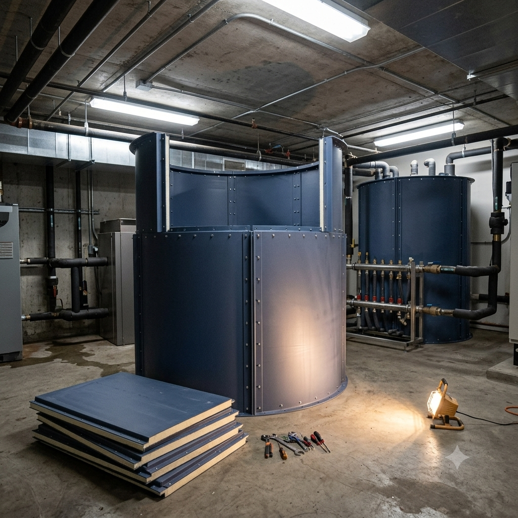
The design response to a constrained path is to change what arrives. If the largest component that must pass through the narrowest opening is a panel rather than a finished vessel, the constraint stops being binding. That is the entire premise of a panelized modular tank: components sized to pass through standard openings, assembled into the finished vessel inside the room. The construction is documented in the technical documentation library.
The honest limit: assembling in place solves the delivery path. It does not solve a room with insufficient floor area, inadequate structure, or no viable position clear of existing equipment. Those are separate constraints with separate answers, and a vendor who answers all four with one feature is overselling.

Water weighs approximately 8.34 pounds per gallon. That single fact drives most of the structural conversation, and it produces numbers that surprise people who have not run them.
A 700-gallon module holds roughly 5,800 pounds of water before the vessel, insulation, fittings, and contents of connected piping are counted. Distributed over the modest footprint a cylindrical vessel occupies, the resulting bearing pressure is on the order of several hundred pounds per square foot. For context, common uniform design live loads for occupancies such as offices and light storage sit well below that range.
Read that comparison carefully, because it is easy to misuse. Bearing pressure under a piece of equipment is not directly comparable to a uniform design live load; a structural engineer converts concentrated and patch loads into an appropriate analysis against the actual framing, span, and construction. The point is not that every filled tank overloads every floor. The point is that the magnitudes are large enough that the question must be asked by a qualified engineer rather than assumed away. The figures above are illustrative, derived from assumed geometry rather than measured product data.
Practically, floor construction sorts retrofit projects into two groups:
It is tempting to assume that splitting a given capacity across more, smaller modules reduces the load on the floor. Run the arithmetic and that is not what happens: for the same total volume at the same vessel height, the combined footprint and therefore the bearing pressure under the vessels is essentially unchanged. The water did not get lighter.
What distribution actually buys you is different, and still valuable. It reduces the weight of each individual unit for rigging and handling. It allows total mass to be spread across a wider area of the floor plate and positioned deliberately relative to beams, columns, and spans, rather than concentrated at one point in the middle of a bay. And it opens the option of splitting capacity across more than one room or level entirely.
It does not, however, exempt anything from analysis. Published code guidance on nonstructural components is explicit that multiple or ganged components in close proximity should be analyzed to confirm the structure will not be overloaded. Distributing load is a design strategy that a structural engineer evaluates, not a way around having one.
Ceiling height is the constraint teams most often measure incorrectly, because the number that governs is not the nominal ceiling height. It is the clear height to the lowest obstruction directly over the tank position, plus everything that has to happen above the tank.
Above the vessel you need the top connections and manifold, room to make and later break those connections, clearance for any anode or access port that must be withdrawn vertically for service, and enough space for a technician to work. A vessel that physically fits with two inches to spare is a vessel nobody can maintain, and in practice that becomes a deferred-maintenance problem that outlives everyone who approved it.
Height also interacts with floor loading in a way worth planning around deliberately. For a fixed volume, a taller narrower vessel occupies less floor area but concentrates its weight over a smaller footprint, raising bearing pressure and raising the center of gravity, which matters for seismic anchorage. A shorter wider vessel does the opposite: easier on the structure and on anchorage, harder on floor area. Low mechanical rooms therefore push you toward geometry that is, conveniently, also gentler on the floor. That is one of the few genuinely free trades available in this kind of retrofit.
Service clearance around the sides matters as much as above. Plan for access to every connection, valve, and control that will need attention, and for the possibility of removing or replacing a module without dismantling the entire bank. Modular construction helps here specifically because a single module can often be isolated and serviced while the rest of the bank stays in operation.
Storage tanks are nonstructural components, and in the United States their seismic design is governed by Chapter 13 of ASCE 7, which is adopted through the IBC and state building codes; ASCE 7-22 Chapter 13 is referenced by the 2024 IBC and the 2025 California Building Code. This applies to the component, its supports, and its attachments to the structure.
Two thresholds bring storage tanks into scope in most projects. Published summaries of Chapter 13 note that anchorage requirements reach components weighing more than 400 pounds, and components whose center of gravity sits more than four feet above the floor. A filled thermal storage module of any meaningful size clears the weight threshold comfortably, and larger vessels clear the center-of-gravity threshold as well. Mechanical and electrical components in the lowest seismic design categories carry exemptions, so the applicable seismic design category is the first thing to establish.
The component importance factor is the next determination. Guidance on Chapter 13 explains that the component importance factor is either 1.0 or 1.5, and that 1.5 applies where the component is required for life-safety function, where it contains hazardous material above thresholds set by the authority having jurisdiction, or where it is in a Risk Category IV structure and needed for continued operation. A domestic hot water storage tank in an ordinary multifamily building and the same tank in a hospital that must remain operational after an earthquake are not the same design problem.
Two practical notes for retrofits specifically. First, ASCE 7-22 revised the horizontal seismic design force equation for nonstructural components, so anchorage calculations carried over from an older project may not be current. Second, post-installed anchors in concrete have long been required to be seismically prequalified, which constrains the anchorage approach in an existing slab whose condition and reinforcement may be unknown. Federal design guidance for nonstructural components provides a thorough treatment of the underlying criteria. Install-side requirements are covered in the contractor resources.
With the constraints established, these are the moves available. Most successful retrofits use three or four of them together.

This is the first thing to check and the most frequently missed. An electrification retrofit that replaces a gas-fired plant removes a boiler, gas-fired water heaters, flue and venting, sometimes a gas train and its clearances, and often an obsolete storage tank. That equipment has a footprint, and required clearances around combustion equipment mean its effective footprint is larger than its physical one. In a meaningful share of projects, the space vacated exceeds the space the new storage needs. Draw the room as it will be after removal, not as it is today, because the room as it is today is not the room you are designing for.
A single large vessel is the simplest hydraulic answer and frequently the worst fit. Splitting the same capacity across several interconnected modules lets you place storage where the room actually has space, work around existing equipment and structure, position mass deliberately relative to spans and columns, and reduce individual unit weight for rigging. Capacity can even be split across separate rooms or levels where the hydraulic design supports it. As covered above, distribution is a design tool evaluated by a structural engineer, not a way around structural review.
Tall and narrow saves floor area but raises bearing pressure and center of gravity. Short and wide does the reverse. Neither is correct in the abstract; the right answer is dictated by which constraint is actually binding in your room. Establish that first, then choose geometry to relieve it.
Modular capacity can be installed in stages: put in what the room and the budget accommodate now, and add modules as loads grow, as a portfolio electrifies building by building, or as adjacent equipment is decommissioned in a later phase. This converts a single large capital request into a sequence, and it means a room that cannot hold the full ten-year requirement today is not disqualified from starting. It also pairs well with the financial case, since deferred capital improves return; see the thermal energy storage ROI calculator.
The mechanical room is a convention, not a requirement. Adjacent storage rooms, an unused portion of a parking garage, a service corridor alcove, a former fuel or flue chase, or an exterior pad can all host storage provided the hydraulic connection, freeze protection, security, and access are properly handled. Slab-on-grade locations are structurally attractive for exactly the reasons discussed above. Roof placement is occasionally proposed and should be approached with caution, because it puts the heaviest element of the system on the structure least likely to have spare capacity.
Where the delivery path is the binding constraint, the decisive specification decision is whether the vessel arrives finished or is built inside the room. Thermal Energy HQ's modular tanks use a patented panelized design for this reason: components pass through standard openings and the vessel is assembled at its final position, then expanded later by adding modules. In a below-grade room reached by a single stair, this is frequently the difference between a viable project and a cancelled one.
For a packaged storage-plus-heat-source configuration see the All-In-One thermal energy system; documented retrofit deployments are in the case studies.
Everything above assumes the building is occupied, because in a retrofit it almost always is. That imposes constraints that have nothing to do with the equipment.
Four cases where the honest answer is that no design strategy avoids construction.
Naming these is not a concession. A team that knows in week one that the room must be expanded can price and schedule it properly. A team that discovers it in week twenty has a problem that costs far more than the construction itself.
Work through this before committing to a design. It is ordered so that the cheapest disqualifying findings surface first.
Usually yes, and the deciding factors are established by survey rather than by building type. Four constraints matter: the access path from the loading dock to the final position, the floor's structural capacity, clear height to the lowest obstruction over the tank position, and seismic anchorage. Where the access path is the binding constraint, equipment that assembles in place from components sized to pass through standard openings frequently resolves it. Where floor structure is the constraint, the answer is structural analysis and deliberate load placement rather than a product feature.
That ends the project for any vessel that arrives finished, because a welded tank's diameter is fixed at the factory and no rigging approach changes it. The design response is to change what arrives: a panelized modular tank ships as components that pass through standard openings and is assembled into the finished vessel at its final position inside the room. Measure clear width rather than nominal door size, and check corridor turn geometry as well, because a component can clear a door and still fail to make the turn beyond it.
Water alone is approximately 8.34 pounds per gallon, so a 700-gallon module holds roughly 5,800 pounds of water before the vessel, insulation, and fittings are counted. Spread over the footprint a cylindrical vessel occupies, the resulting bearing pressure runs to several hundred pounds per square foot, which is large enough that a structural engineer must evaluate it against the actual floor construction. Slab-on-grade placement is usually straightforward; a suspended slab requires analysis.
Not in the way people expect. For the same total volume at the same vessel height, the combined footprint and the bearing pressure under the vessels are essentially unchanged, because the water does not get lighter. What distribution does buy is lower individual unit weight for rigging, the ability to spread total mass across a wider area of the floor plate and position it deliberately relative to beams and spans, and the option of splitting capacity across rooms or levels. Code guidance is explicit that ganged components in close proximity must still be analyzed together.
In most projects, yes. Storage tanks are nonstructural components governed by Chapter 13 of ASCE 7, which is adopted through the IBC and state building codes. Published summaries note that anchorage requirements reach components weighing more than 400 pounds and components whose center of gravity is more than four feet above the floor, and a filled storage module of any meaningful size exceeds the weight threshold. The applicable seismic design category and the component importance factor, which is either 1.0 or 1.5 depending on life-safety function and facility risk category, are determinations for your engineer.
The room you have may be enough, but only if feasibility is established before sizing. Survey the full access path, floor construction, clear height, service clearances, and seismic requirements first. Then use removals, distributed capacity, geometry, phasing, adjacent space, or equipment that assembles in place to address the constraint that actually binds.
And if the structure, access path, floor area, or required clearances make the project impossible, identify that early. An honest expansion decision in week one is better than a failed retrofit in week twenty.
Tell our team about your building, operating goals, and energy needs.