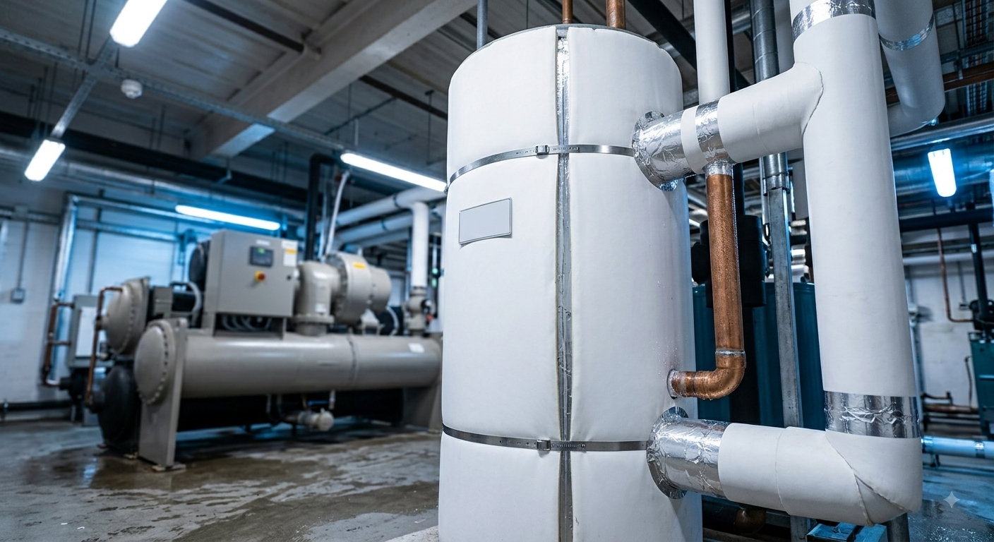
A buffer tank is sized by subtraction, not by multiplication. The number that matters is not gallons-per-ton times tons — it is that figure minus the water the system already contains. Skip the subtraction and you specify a tank that duplicates volume already sitting in the piping, which is how a project ends up paying for a 2,000-gallon vessel it needed 400 gallons of.
A chilled water buffer tank adds thermal mass so a chiller can complete a minimum run cycle without the return water temperature satisfying the setpoint too quickly. Sizing has three steps: establish the required system volume from the chiller manufacturer’s minimum, calculate the volume the system already holds in piping, evaporator, and terminal equipment, and subtract. Common starting points run from roughly 2–6 gallons per ton for comfort cooling to 6–12 gallons per ton where temperature control is tight, but those are rules of thumb; the governing number is the chiller’s own minimum system volume and its allowable starts per hour.
Before specifying anything, check three things — whether existing volume already satisfies the requirement, whether the real problem is load shifting rather than cycling, and whether a low delta-T is inflating the calculation.
Key Takeaways
A chiller cycles off when the return water temperature satisfies its setpoint. In a system with little water in it, a small load cools that small volume very quickly, the chiller shuts down, the load warms the volume again just as quickly, and the compressor restarts. Repeat.
The consequences are well documented: accelerated compressor wear, higher energy use per ton delivered, unstable supply temperature, and in refrigerant terms the risk of liquid floodback and oil migration. Most chillers also carry a hard limit on allowable compressor starts per hour — commonly around three — and once that limit is hit the machine locks out. A building can lose cooling not because the chiller is too small, but because the system holds too little water.
A buffer tank fixes this by adding mass. More water means the loop temperature moves more slowly, which means the chiller runs longer before it satisfies setpoint. That is the entire function.
In this article
Buffer tank or storage tank? Answer this before sizing anything

A buffer tank provides minutes of thermal mass so the chiller completes a run cycle. It is sized from the chiller’s minimum system volume requirement, typically in gallons-per-ton terms.
A chilled water storage tank provides hours of cooling capacity so chiller operation can be moved to off-peak periods. It is sized from a load profile and a discharge duration, and its purpose is economic rather than mechanical.
The two are frequently conflated, and the failure modes run in both directions: a buffer tank will not shift load, and a storage tank sized without regard to minimum volume may still permit short cycling at light load. If the problem is a demand charge or a time-of-use spread rather than a cycling chiller, you are looking for storage, and this article is the wrong calculation.
The sizing method: five steps
Step 1. Get the chiller manufacturer’s minimum system volume
This is the governing input and it belongs first. Manufacturers publish a required minimum system volume — usually as gallons per ton — along with a maximum allowable number of compressor starts per hour. Where those two figures exist, they override every rule of thumb below.
Published starting points, for orientation only, are shown below. These are industry and manufacturer rules of thumb rather than a code requirement. Reference data on chilled water system volume and minimum cycle protection appears in the ASHRAE HVAC Systems and Equipment Handbook, which requires a subscription or purchase.
Step 2. Calculate the required system volume
Required system volume
RSV (gallons) = chiller capacity in tons × required gallons per ton
Worked example: a 100-ton chiller at a manufacturer-specified 5 gallons per ton requires 500 gallons of total system volume.
Step 3. Calculate the volume the system already contains
This is the step that gets skipped, and it is where the money is. Every foot of pipe, every coil, and the evaporator barrel itself all hold water that already contributes.
Worked example, continuing: 198 gallons of piping plus 35 gallons of terminal equipment gives an actual system volume of 233 gallons.
Step 4. Subtract
Buffer tank volume
Buffer tank (gallons) = required system volume − actual system volume
Worked example: 500 − 233 = 267 gallons. Round up to the next available standard size.
If the result is zero or negative, no buffer tank is required. That outcome is more common than the market for buffer tanks would suggest, particularly in buildings with long distribution runs, large-diameter piping, or substantial coil volume.
Step 5. Verify against run time, not just volume
The gallons-per-ton method is a proxy. What actually matters is whether the chiller achieves an acceptable minimum run time at its minimum load, and that is a different calculation:
Run-time check
Volume required (gallons) = (chiller minimum output in Btu/h × run time in hours) ÷ (500 × allowable temperature swing in °F)
Where 500 is 8.33 lb/gal × 60 min/hr. Solve for the volume that delivers the target run time — commonly ten to fifteen minutes — at the lowest load the building actually presents.
Take the larger of the Step 4 and Step 5 results. Where a chiller unloads deeply, the run-time check frequently governs and can exceed the gallons-per-ton answer substantially.
That last point is counterintuitive and worth stating plainly: a chiller with excellent turndown needs more buffer volume, not less. A machine that unloads to 10% of capacity can satisfy a small load very quickly, so protecting its run time takes more mass than protecting a machine that only unloads to 40%.
Three checks that often shrink the tank — or eliminate it
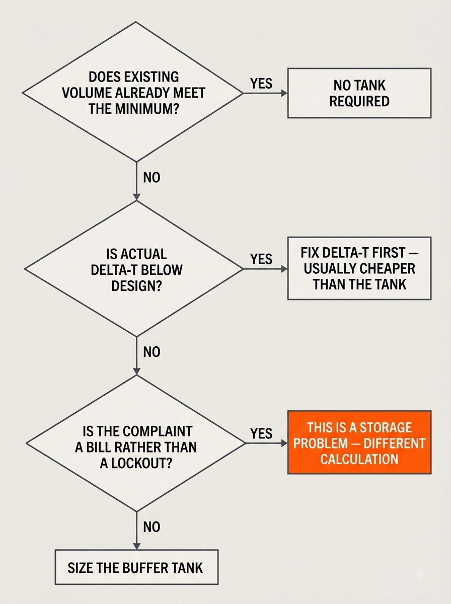
Checks one and two frequently reduce the specification. Check three sometimes redirects the project entirely — which is a better outcome than a correctly sized tank that solves the wrong problem.
Placement and piping: where the volume has to sit
A correctly sized tank in the wrong place does not protect the chiller. Three configuration points matter.
In variable primary flow systems the tank also serves a hydraulic function, adding volume to extend cycle times while decoupling the primary chiller loop from secondary distribution so that reductions in secondary flow do not create low-flow conditions at the evaporator.
And insulate it. A chilled water tank in an unconditioned mechanical space gains heat and sweats. Insulation thickness is selected from tank temperature against maximum ambient temperature and humidity, and a vapour barrier is not optional in humid climates.
Worked example, end to end
Illustrative teaching sequence, not a design output. Confirm every input against the chiller submittal, and have the result reviewed by the mechanical engineer of record.
Two notes on the result. First, round up to the next standard size — the calculation produces a minimum, not a target. Second, if the run-time check in Step 5 returns a materially larger number, that is the number to use, and it usually means the chiller unloads more deeply than the gallons-per-ton rule assumes.
Illustrative chilled water buffer tank sizing example
StepInputResult
Chiller capacity100 tons—
Manufacturer minimum5 gallons per ton—
1–2. Required system volume100 × 5500 gallons
3a. Piping volume300 ft of 4-inch at ~0.66 gal/ft198 gallons
3b. Terminal equipmentFrom submittals35 gallons
3. Actual system volume198 + 35233 gallons
4. Buffer tank by subtraction500 − 233267 gallons
5. Run-time checkAt minimum chiller output and target run timeTake whichever is larger
When the answer is storage instead
A meaningful share of people sizing a buffer tank are solving the wrong problem, and it is worth being explicit about the tell.
The tell is the complaint. If the symptom is nuisance lockouts, compressor wear, or unstable supply temperature at light load, that is a cycling problem and this article’s calculation applies. If the symptom is a bill, it is not — and no amount of buffer volume will change a demand charge.
Where the driver is economic, the sizing logic changes completely: the calculation runs from a peak block, a discharge duration, and a tariff rather than from a chiller’s minimum volume. That method — and the derates that separate nameplate volume from usable capacity — is worked through in How to Size Thermal Storage Tanks for Peak Hot Water Demand (the arithmetic transfers; the temperatures do not), and the tariff mechanics in Peak Shaving vs Load Shifting. The equivalent buffer-versus-storage question on the heating side is covered in Buffer Tank vs Storage Tank: Do You Need a Buffer Tank for a Heat Pump?.
Buffer tank versus storage tank
Buffer tankStorage tank
PurposePrevent chiller short cycling
Sized fromChiller minimum system volume and minimum run time
Duration of usefulnessMinutes
Governing constraintMechanical — compressor protection
Typical driverNuisance lockouts, temperature swing, compressor wear
Volume order of magnitudeGallons per ton, single digits to low tens
A specification checklist
Items nine and ten are the ones that surface late and cost the most. The access constraint in particular decides feasibility in existing buildings more often than the thermal calculation does — a constraint covered in Designing Thermal Storage for Existing Buildings Without Major Mechanical Room Expansion.
Frequently Asked Questions
How do you size a chilled water buffer tank?
By subtraction. Multiply chiller capacity in tons by the manufacturer's required gallons per ton to get the required system volume, calculate the volume the system already contains in piping, terminal equipment, and the chiller evaporator, and subtract the second from the first. The difference is the buffer tank volume. Then verify the result against a run-time calculation at the chiller's minimum load, and use whichever number is larger.
How many gallons per ton does a chilled water buffer tank need?
Commonly cited ranges run from roughly 2 to 6 gallons per ton for nominal comfort cooling, and 6 to 12 gallons per ton where temperature accuracy is critical, with around 10 gallons per ton frequently cited for data centre applications. These are industry and manufacturer rules of thumb rather than a standard. The chiller manufacturer's own required minimum system volume and allowable starts per hour govern.
Do I always need a buffer tank on a chilled water system?
No. If the volume already held in piping, terminal equipment, and the evaporator meets or exceeds the manufacturer's required minimum system volume, no buffer tank is required. This is more common than expected in buildings with long distribution runs, large-diameter piping, or substantial coil volume, and it is why counting existing volume before specifying a tank is worth the effort.
What is the difference between a buffer tank and a chilled water storage tank?
A buffer tank adds minutes of thermal mass to stop a chiller short cycling and is sized from the chiller's minimum system volume requirement. A chilled water storage tank provides hours of cooling capacity so chiller operation can be shifted to off-peak periods, and is sized from a load profile and a discharge duration. The first solves a mechanical problem, the second an economic one, and they are sized by completely different logic.
Why does a chiller with better turndown need a larger buffer tank?
Because it can satisfy a small load very quickly. A chiller that unloads to 10 percent of rated capacity will drive the loop temperature to setpoint faster at light load than a machine that only unloads to 40 percent, so protecting its minimum run time requires more thermal mass, not less. This is why the run-time check at minimum load often governs over the gallons-per-ton rule of thumb.
How does delta-T affect buffer tank size?
Inversely. Required volume is proportional to the energy that must be absorbed divided by the allowable temperature swing, so halving the temperature differential roughly doubles the volume required for the same protection. A system suffering from low delta-T syndrome will calculate a much larger tank than its design would suggest, which is why investigating and correcting the delta-T problem is usually cheaper than buying the tank it would otherwise require.
Where should a chilled water buffer tank be installed?
On the primary loop, between the chiller and the primary-secondary interface, so it stays in full thermal contact with water the chiller is actively conditioning. Return-side placement is the usual choice where the goal is cycling protection. Connections should be arranged so flow cannot short-circuit between inlet and outlet, because a tank that is bypassed internally contributes only a fraction of its volume.
Does a buffer tank reduce demand charges?
No. A buffer tank holds minutes of thermal mass, which is enough to protect a compressor but far too little to move a chiller's electrical load out of a billed peak interval. Reducing a demand charge requires storage sized in hours against a load profile and a tariff, which is a different tank and a different calculation.
Conclusion
Sizing a chilled water buffer tank is one of the more forgiving calculations in mechanical design, provided the three inputs are real: the manufacturer’s minimum system volume, the volume the system already contains, and the chiller’s behaviour at minimum load. Get those and the arithmetic is short.
The errors are equally consistent. Not counting existing volume produces a tank that duplicates water already in the pipes. Ignoring the run-time check at deep turndown produces one that is too small. And sizing a buffer tank when the actual complaint is a utility bill produces a tank that works perfectly and changes nothing.
Count what you have, ask the chiller what it needs, and check which problem you are solving before anyone quotes a vessel.
Thermal Energy HQ manufactures modular thermal energy storage for hot water and heating applications. This article is published as an engineering reference; sizing figures should be confirmed against the chiller manufacturer’s documentation and reviewed by the mechanical engineer of record.